RIGHT STUFF, Inc.Right Stuff Wrong StuffGX250 (XS400) FET Regulator I made a "FET Regulator" for my YAMAHA GX250. Original regulator was working very well. I had no needs to swap regulator but I had a curiosity. And My old XS650(Tirill type) needs smart regulator. At First, I checked the original regulator. I prepared the power supply and 5ohm resistor instead of field coil. Regulator shut the current to resistor(=field coil) at over 14.7V. There is no definite hysteresis. Voltage drop of regulator is 0.88V at 2.5A. There is a power Tr(Darlington?) in the regulator. Next, I checked the existence of Flywheel Diode. There was a Flywheel Diode between green wire and brown wire. Voltage drop is 0.93V at 2.5A. It is not Schottky type maybe.
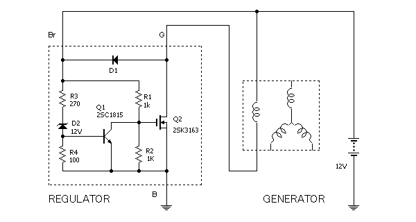
I was designing the circuit with OPamp first. But I found the simple circuit in the old schoolbook of technical high school. It uses zener diode and is very simple. I adopted it. I chose FET instead of Power Tr. Because voltage drop of FET will be under 0.1V. And "FET Regulator" is cooler than "Transistor Regulator" in my feelings. Zener diode D2 makes reference voltage. Vz is 12V. If Vz is more nearly 14.5V the control will be more sensitive. Zener diode needs 5mA current. When the regulator is balanced voltage of R4 is 0.5-0.6V. It is equal to Vbe of Q1. The voltage of R3 is remains. All small signal NPN Tr is acceptable for Q1. 2SC1815 is very popular and not expensive in Japan. The performance of 2SK3163(60V-75A) is excessive for this application but it costs only 200yen at AKIZUKI-DENSHI in AKIHABARA. If voltage of battery exceeds the limit(=14.5V), Q1 turns-on and ties down the gate of FET to the ground. D1 is flywheel diode for field coil. When FET shuts the current suddenly D1 works. There is no hysteresis so it may be good PWM controller with luck.
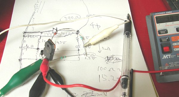
I made the prototype at first. Best Value of R3 was 390ohm in my calculation but actually, limit voltage was 15.2V. It is too high. I adjusted the value of R3. 330ohm-->14.8V, 270ohm-->14.4V, I adopted 14.4V. The wiring of motorcycle is not sturdy as car. If I move the detecting point controled voltage will be changed(0.2V-0.5V) easily. Sensitive adjustment means nothing. Voltage drop of regulator is 18mV at 2.5A. It's a great improvement electrically.
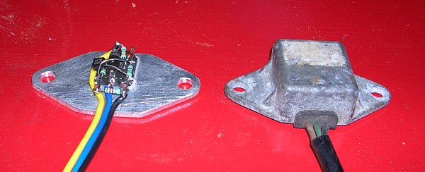
Right one is YAMAHA's regulator. Left one is my regulator. I placed all parts on the aluminum board(t=3.0mm). It has same dimension as YAMAHA for compatibility. Finally, I covered all parts with epoxy. There is no dramatic improvement when riding. But I will make regulator for old XS650. EFT regulator will bring good reliability than Tirrill regulator.
Some people send E-mail to me. "Can I use this regulator for my motorcycle?" But, I can't understand your situation. I can't answer... This regulator controls the current of field coil. And It operates at minus side of coil. If your motorcycle has permanent magnet type generator, this will not work on your motorcycle. If your regulator controls plus side of coil you need re-wiring or re-design with "2SJ***" type FET.
|